I SPI With My Little Eye
Just got back from a drive to the electronics parts store. I’m glad hobbyist electronics has seen a resurgence… I remember hearing about Fry’s and AllMicro closing when I was younger and being really sad. Apparently there used to be something called RadioShack that was in that register, too. But now hobbyist electronics is big again and we have a pretty big store for it in a city near where I live. (Not saying the name cause I am probably-overly concerned with information security.)
I purchased:
- Beginner’s breadboard kit, includes a few breadboards, jumper cables, a bunch of common components like resistors, capacitors, netennas, etc, and some common ICs. And an instruction manual for how to assemble some common circuits.
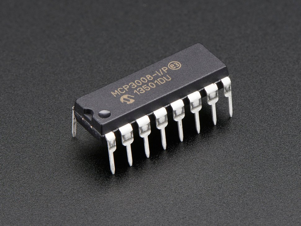
- An MCP3008 SPI ADC DIP chip, which is more acronyms than I want to deal with on a Friday night.
- A Turbo Chicken Crunchwich, because I have no regard for my well-being and I was hungry.
Let’s break down the SPI ADC DIP part, in reverse order cause it gets increasingly complicated that way.
DIP: Dual Inline Package
DIP is just the name for the form factor. It’s the kind you can stick in a breadboard, as opposed to the kinds you need to solder or sonicweld. The ones that look like little insects.
Here’s a picture of the chip I found online, for reference.
ADC: Analog to Digital Converter
This is what the chip does. It converts analog signals to digital signals.
My computery brain liked this explanation: it converts floats to ints. The MCP3008 takes analog signals in, and outputs 10-bit signals.
The range of the float input in volts goes from 0 volts to a reference voltage you stick on one of the pins, which
looks like it can be about 5 volts maximum. The int output goes from 0 to 2^10 = 1024.
Basically it does this.
def adc(voltage):
    return int(voltage / 5 * 1024)
SPI: Serial Peripheral Interface
This is how the data gets from the chip to the Raspi.
One thing you might have been wondering (based on the fact that I was wondering it) is how you get those 10 bits of information from the chip to the Pi. The chip only has 16 pins, and with 10 taken up by data that’s only 6 pins left for power, ground, timing, or whatever. (I don’t actually remember what all the pins do). On top of that, the MCP3008 has 8 channels, so one chip can read 8 analog signals at once. You’re out of pins! And imagine if you had a more precise chip that could do 32-bit precision or something.
So some very smart people invented SPI, the Serial Peripheral Interface.
- Serial: the data is transmitted serially, one bit at a time.
- Peripheral: it’s used to interact with peripheral stuff, so anything that isn’t the main computer. In this case the peripheral is the MCP3008 of course.
- Interface: how the peripheral and computer talk to each other. (Yes, I know you know what interface means, but it would be weird to leave one off.)
This kind of thing is way more up my alley, so I understand it pretty well. Using SPI, a computer and peripheral can transmit/receive any amount of data using only 4 pins. The MCP3008 has 4 pins dedicated to SPI, while you can use software to configure any 4 GPIO pins on the Raspi to be the 4 SPI pins. (I guess that’s what makes them General Purpose I/O.)
Pins 1 and 2 are the MISO and MOSI pins, aka the Main In/Subordinate Out and Main Out/Subordinate In. This is the pin that data is transmitted over; the Raspi is the “main” and the MCP3008 is the “subordinate”. As best as I can tell from the horridly dense datasheet, 10-bit integers are transmitted over the MISO from the ADC to the Raspi, and configuration info like which analog signal to transmit is sent over MOSI from the Raspi to the ADC.
Pin 3 is the clock pin. This is toggled up and down really fast by the Raspi and used to synchronise when the information is transmitted. Whenever the Raspi puts voltage on that pin, it and the subordinate read whatever is on their respective in pins.
And Pin 4 is the chip select pin. If it’s high, then the subordinate will quit working until it becomes low. This way you can use 1 main with many subordinates, and only have 1 extra pin on the main for each new subordinate, by selecting which chip is active at any given time.
I’m hoping to get some code reading values out of the MCP3008 tomorrow at robotics club. I’m not sure if I want to hook it up to the BCI devkit yet just because it will be hard to control, so I won’t know if it’s working or not. I think Kyra can get a dial going so that I can turn it and have it send 0 to 5 volts to the chip, so I’ll do that for testing purposes.